
BD OWLjet 70mm EDF 6s LiPo Battery
3D Printed RC Plane Jet
~ Catapult & Landing Gear Versions ~


Suggested RC Pilot Skill Level
BD OWLjet Landing Gear Version is for advanced skill RC pilot

BD OWLjet Catapult Version is for intermediate skill RC pilot

BD OWLjet 70mm EDF
Drawing inspiration from Jim Bede’s iconic designs, the BD OWLjet 70mm EDF 3D printed RC plane combines a sleek, vintage aesthetic with modern 3D-printing versatility. It is engineered for ease of assembly, spacious electronics management, and—most importantly—an exhilarating flight experience.
Construction & Material Recommendations
The BD OWLjet is compatible with both PLA and LW-PLA, but your choice of material significantly impacts flight performance:
The Gold Standard (LW-PLA): For the best performance, we recommend printing the entire model in LW-PLA. This achieves a Wing Cube Loading (WCL) of 16.9, placing it in the “light jet” category for excellent gliding and slow-speed handling.
The “Digital Balsa” Method: To balance strength and weight, print with LW-PLA and 3% infill. We call this “digital balsa and foam”—it’s incredibly rigid while remaining remarkably light.
Hybrid Builds: You can mix materials (e.g., a PLA fuselage with LW-PLA wings). We provide specific G-code and optimized STL groups for PLA, LW-PLA (no infill), and LW-PLA (with infill) to ensure success regardless of your setup.
⚠️ A Note on Weight: A full-PLA build with landing gear exceeds 3kg, which we consider too heavy. For the landing gear version, we strongly suggest using LW-PLA to keep the All-Up Weight (AUW) within a manageable range.
Power System & Battery
The BD OWLjet is designed for a 70mm EDF setup. Due to the AUW range (1,950g to 2,850g), we recommend the following:
Requirement: 6S LiPo configuration only.
Thrust: Aim for a minimum of 2kg of thrust.
Landing Gear Version: We recommend a high-performance 6S inrunner motor to ensure you have the power needed for takeoffs, especially when flying from grass.
Flight & Launching Tips
Whether you are a seasoned pilot or a newcomer to EDFs, we want your maiden flight to be stress-free.
Catapult Launching: If you aren’t comfortable hand-launching, we highly recommend the OWLplane Catapult Launcher. It eliminates “human error” and allows you to focus on the controls immediately.
Field Conditions: While the OWLjet can handle grass runways, it performs best on smooth, prepared surfaces.
The “Maiden” Strategy: We suggest starting with the LW-PLA Catapult Version. It’s the easiest way to get familiar with the flight characteristics and trim your surfaces without the pressure of a manual toss.
Please note that you would have better experience with when printed the catapult version with LW-PLA filament. If you are an experience rc pilot and get used to fly the EDF jet, you will find it very easy and fun model. Now, it is up to you to pick what model versions and what filaments to print with.

*) Click the table above to read the table !
How to Find the STL Files and/or g-code Files :
All STL and g-code files can be found under 5 directories as follow “OWL BD OWLjet 70mm – STL and G-code v1.0”,
1. FUSELAGE 70mm
2. WINGS 70mm
3. STABILIZERS 70mm
4. CANOPY 70mm
5. LANDING GEARS 70mm
For example, below is when printing BD OWLjet Landing Gear version with LW-PLA without infill,
STL files :
1. FUSELAGE 70mm, “OWL BD OWLjet 70mm – STL and G-code v1.0\1. FUSELAGE 70mm\STLs\LANDING GEAR VERSION\LW-PLA\NO INFILL” (please select NO INFILL instead of WITH INFILL).
2. WINGS 70mm, “OWL BD OWLjet 70mm – STL and G-code v1.0\2. WINGS 70mm\STLs\LANDING GEAR VERSION\LW-PLA\NO INFILL” (please select NO INFILL instead of WITH INFILL).
3. STABILIZERS 70mm, “OWL BD OWLjet 70mm – STL and G-code v1.0\3. STABILIZERS 70mm\STLs – BOTH CATAPULT & LG VERSIONS\LW-PLA\NOINFILL” (please select NO INFILL instead of WITH INFILL)..
4. CANOPY 70mm, “OWL BD OWLjet 70mm – STL and G-code v1.0\4. CANOPY 70mm\STLs – BOTH CATAPULT & LG VERSIONS\LW-PLA” (no option provided since we have already picked/designed the best STL files to print for the canopy).
5. LANDING GEARS 70mm, since all printed with PLA, there is no need to have separated directories (all using the same STL files).
g-code files :
1. FUSELAGE 70mm, “OWL BD OWLjet 70mm – STL and G-code v1.0\1. FUSELAGE 70mm\G-code\LANDING GEAR VERSION\LW-PLA\NO INFILL\G-code”.
2. WINGS 70mm, “OWL BD OWLjet 70mm – STL and G-code v1.0\2. WINGS 70mm\G-code\LANDING GEAR VERSION\LW-PLA\NO INFILL\G-code”.
3. STABILIZERS 70mm, “OWL BD OWLjet 70mm – STL and G-code v1.0\3. STABILIZERS 70mm\G-code – BOTH CATAPULT & LG VERSIONS\LW-PLA\NO-INFILL\G-code”.
4. CANOPY 70mm, “4. CANOPY 70mm\G-code – BOTH CATAPULT & LG VERSIONS”, continue by selecting desired filament type to print.
5. LANDING GEARS 70mm, “OWL BD OWLjet 70mm – STL and G-code v1.0\5. LANDING GEARS 70mm”, continue by following the options.
Do the same when you pick for Catapult or Landing Gear version when printed with PLA or LW-PLA with or without infill.
Please note, even if you print using LW-PLA or PLA filament type, you may pick to print with PETG filament type for having glass transparent parts such as for LED skins. Also, you may pick PLA when selecting LW-PLA option since some parts are required to print with PLA (stronger if compared to LW-PLA). Would recommend to keep browsing all directories to have better understanding and it should have self explained by their directories and file names.
BD OWLjet Landing Gear Version Videos
Landing Gear Version Videos

4:27

3:29

2:50
BD OWLjet Catapult Version Videos
Catapult Version Videos

2:32

2:32
Some Landing Gear Version Pictures


Summary for BD OWLjet 70mm Special Notes
- Please plan what model version and filament type that you would like to print with.
- Selected model and filament type will determine what is the pilot skill level that you need to have.
- There are two EDF location options when installing the EDF. It will help to meet the targeted CoG location. Please also use respective EDF bracket to install.
- Feel free to put the ESC since it does have spacious front side room to put on. The ESC location can help also to meet the targeted CoG location.
- When printing with LW-PLA and to avoid many travels, some parts are designed so that you need to cut some areas right after.
- Since PrusaSlicer has removed “Ensure vertical shell thickness” option and to prevent many travels, it needs to set “Height range Modifier” values as a workaround otherwise it will generate many travels. It applies only for LW-PLA with no infill.
- Pay attention that “NOSE-LG-SUPP-BLOCK # GR3” is part of the fuselage. It needs to be glued along with assembly parts.
- Do not forget to use nose landing gear brace to protect the nose landing gear from excessive force during landing and take off.
- Avoid to hand launch the model but please use the catapult instead.
- If you plan to print the landing gear version and to use 3D printed landing gears, instead of utilizing NBR O-ring, it is better to utilize pullback springs.
PLA vs LW-PLA w/ infill vs LW-PLA wo/ infill
BD OWLjet 70mm EDF 3D printed RC plane can be printed using PLA and/or LW-PLA. When printed with LW-PLA, both approach “Digital Balsa”/single perimeter and “Digital Balsa and Foam” approaches are provided. Due to material and their model printing approach some sets of STLs including g-code files are grouped into some directories as described on above section. Advantages and disadvantages are already explained above also (please refer to the two tables above).
We call it “Digital Balsa and Foam” approach when the model is printed with LW-PLA using 3% gyroid infill. It give more strength when compared when printed with only using 1-perimeter only.
As you can see from the pictures below, they illustrate a 3D printed part when using gyroid infill and ribs. You can pick infill percentage to you preferences where the higher you set it will be stronger. To get optimal result, we also still use ribs so that we will achieve parts using optimal gyroid infill percentage. With having gyroid infill, we have tried to use top and bottom layers. The good news is that the AUW is still acceptable for the jet and allow it to use like lego style blocks to assemble.
We run some research and experiment with some number of setting values for infill percentage. Final values will be used in our OWLplane slicer profiles. Feel free to increase or decrease the values including playing with other settings if you feel better than ours (we are happy listening / getting your input/feedback, so keep us posted about your build in our facebook group).

*) Below is from F16 part for illustration.


Easy to Assembly Model
Like Playing Lego :
As explained above, click the right side youtube video showing how to assembly the fuselage like playing “lego” blocks.
Expected Some Stringing but Easy to Clean When Printed with LW-PLA :
Since active foaming filaments such as LW-PLA is not affected by retraction, some stringing are expected. The good news is that they are easy to clean compared to printing with standard PLA/PLA+.
Note : sample parts from F16 model.
- Suggested using knife to clean initially.
- Once completed using knife, continue using sandpaper for sanding some strings that still attached to skin.
- Sandpaper could also used to make smoother skin.
- For the plug-in blocks, also use sandpaper to eliminate excessive materials.


Sandpaper Cleaning the Excessive Materials Surrounding Plug-In Blocks :
Sanding parts would make assembling much easier and clean. Excessive materials can be found on the top surfaces. For example, the circle in the picture need to sand so that there is no need to push the part later to fit into the next part.
Note : sample parts from F16 model.

Sand The Surfaces To Get Smooth Ones :
Comparing surfaces before and after sending it. LW-PLA material let you smoothing surfaces where it would not be applicable with standard PLA or PLA+.


Specification and Some Details
Landing Gear Version
Specification (Recommend Only Printed with LW-PLA either w/ or w/o Infill)
- Wing Loading : 107.6-120.3gr/dm^2.
- AUW/Flying Weight : 2550-2850gr (with battery 3300mAh - 4500mAh 6s).
- Wing Area : 23.7 dm^2.
- Wing Cube Loading (WCL) : 22.1-24.7.
- Flight Performance Category : Racer.
- Radio Channels : Throttle, Aileron, Flap, Rudder, Nose Steering LG and Elevator.
- Length : 1,103 mm.
- Wing Span : 1,177 mm.
Power Requirement
- 6s 70mm EDF - inrunner only.
- 3300mAh-4500mAh 6s Battery (about 550gr - 650gr in weight)
Catapult Version
Specification (Best is Printed w/ LW-PLA either w/ or w/o Infill)
- Wing Loading : 82.5-94.9 gr/dm^2.
- AUW/Flying Weight : 1950-2250gr (with battery 2200mAh-3300mAh 6s).
- Wing Area : 23.7 dm^2.
- Wing Cube Loading (WCL) : 16.9-.19.5.
- Flight Performance Category : Racer.
- Radio Channels : Throttle, Aileron and Elevator.
- Length : 1,103 mm.
- Wing Span : 1,177 mm.
Power Requirement
- 6s 70mm EDF - outrunner or inrunner.
- 2200mAh 6s to 2800mAh 6s Battery (about 400-500gr in weight)
Center of Gravity (CoG) :
- CoG is 92mm from Wing Root Leading Edge (see the pictures below).


Spar Requirements :
- 1 x 8mm OD and with 750mm long fiber carbon tube as front fuselage and wing spar.
- 1 x 8mm OD and with 1000mm (1M) long fiber carbon tube as back fuselage and wing spar.
- 1 x 6mm OD and with 465mm long for stabilizer spar.
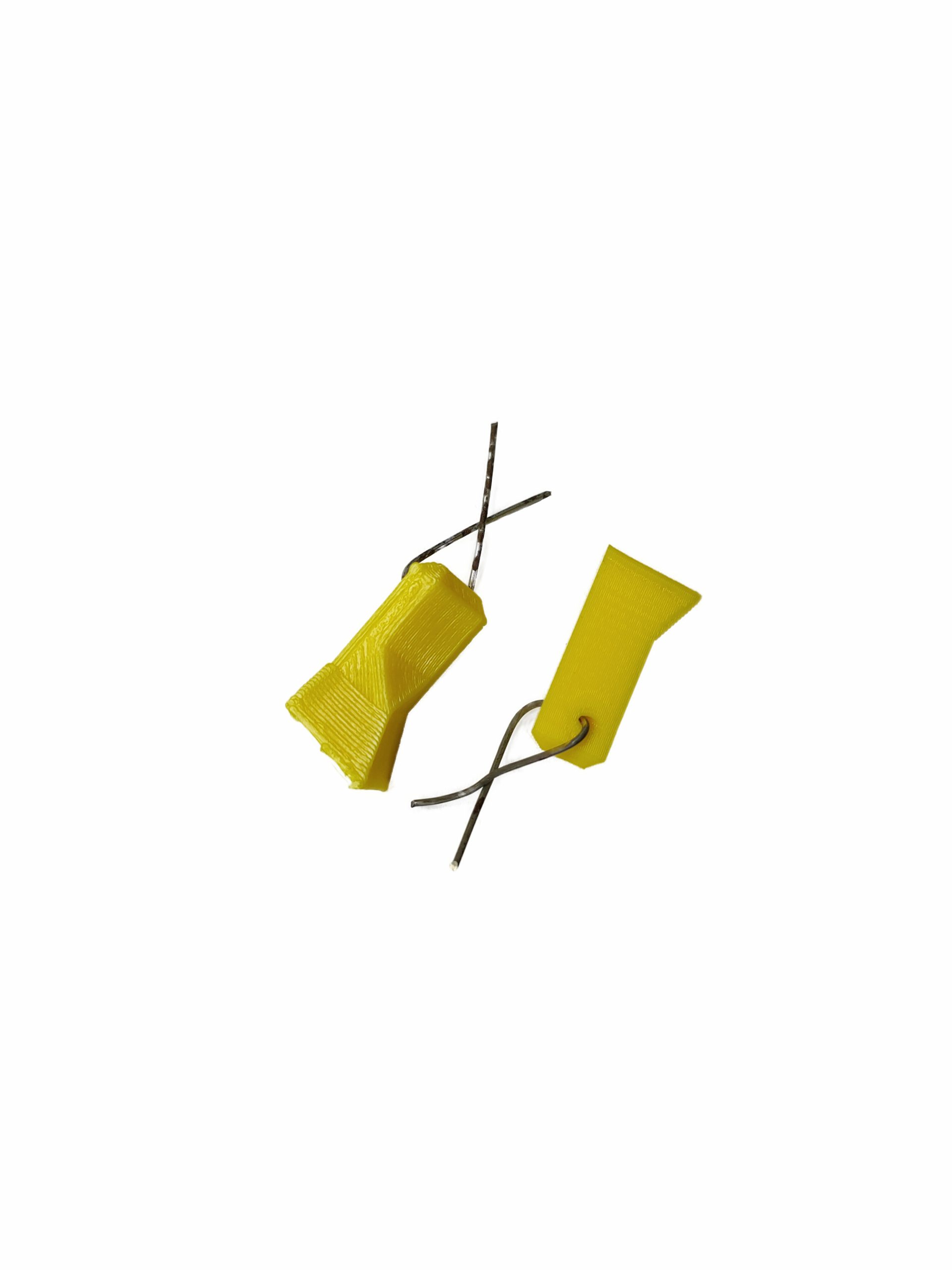
Locking Belt for Attaching Wings to Fuselage :

Left is for Catapult version and Right is for Landing Gear version :
Aileron/Wing Control Surfaces Rods :

Aileron/Flap/Wing Control Surfaces Rods :

No Rudder Control Surface Used on the Right Side Picture (Can Pick Either One of Them)


The Following is for Both Catapult version and Landing Gear version :

Canopy Assembly Support Rod and Pins :
See below figures to assembly the Canopy by using 2.5mm support rod.


Cutting Some Areas for LW-PLA Parts :
Due to avoid stringings for LW-PLA parts, some parts are designed so that minimum travels are required to print the parts. Some areas need to close since vase mode can not be achieved if a particular layer has more than one island. Below are some of fuselage parts that are affected by the vase mode design.


Nose Landing Gear Support is Part of FUSELAGE :
When assembling the fuselage, the “NOSE-LG-SUPP-BLOCK # GR3” should be part of the fuselage. If, in case, you miss to include that parts, try to force the part into the fuselage (when printing using LW-PLA, we have successfully inserted into the fuselage). Please glue the “NOSE-LG-SUPP-BLOCK # GR3” after already in its place. The following pictures show it :
During Assembly :


After Assembly :


Installing Nose LED, Left and Right Wing LEDs :
Try to find transparent filaments either PLA or PETG filaments to print LED parts. It may be easier to find transparent PETG type of filament rather than PLA. In the repository, the PETG gcode files are provided in case you would like to print them using PETG. 3MF PrusaSlicer files are also provided in case you would like to change the setting values to suite your 3D printer need.
After printing the parts, you need to drill a hole using 5.5mm drill so that the LED can be inserted into the parts. Feel free to glue LED into the parts using CA or hotglue.


Try to search and find similar LED navigation LEDs as shown on the above pictures. You can find them using Aliexpress.com or any other hobby stores.
Make sure the LED diameter is 5mm. The following right side pictures show the 5mm LEDs that can fit also for the model for your reference but you need to do it yourself turning on the LEDs using available power source in the model.


- Use hot glue to attach the LED into its holder.
- Push the holder to its place when attaching it to the fuselage or wings.
- Please watch the right side video showing how to install LEDs into the model.
- See @6:45 for Nose LED
- See @0:25 for Wing LED
Installing LEDs Videos
2:33
2:33
EDF and Electronic Positions :
Feel free to locate the electronics for getting the correct CoG.
BD OWLjet 70mm Catapult Version (below is from 64mm EDF version, it should be similar to 70mm EDF Catapult Version):


BD OWLjet 70mm Landing Gear Version :


Two EDF Location Options to Meet the CoG Position
Two EDF locations are provided so that it would be easier to meet the CoG location by your preferred LiPo battery weight. The red color bracket in the following picture is the long one where the yellow color one is the short one. When installing the long one, you need to push the EDF and the bracket into the fuselage until it can not move anymore. For the short one, just put the EDF and the bracket as shown in the following picture. When you find the battery weight is not enough to meet the CoG, please use the long one. Whenever you need to use bigger battery, you may need to use the short one.


Closer to The Front Side Bracket


Closer to The Back Side Bracket


EDF Installation w/ Fixed Leading Edge Lip and Removed Leading Edge Lip :
Left picture is EDF installation with leading edge lip (you need screws to install) and right picture is EDF with no leading edge lip (you do not need screws to install but need to remove leading edge lip). You can use your 70mm EDF with its leading edge lip still attached using generic provided bracket. When using removed intake lip, please glue using hot glue the EDF to the bracket.
If you have 70mm EDF and would like to test if the bracket fits with your brand of EDF, feel free to download the bracket by clicking the button below (the long version will be available when you purchase the model – below is for you to test only) :
Using Short Version (Better for Heavier Battery)


Using Long Version (Better for Lighter Battery)


*) Only short version bracket shown in the following


For BD OWLjet Catapult Version
How to Launch BD OWLjet 70mm EDF Model :
Two methods are suggested to launch the model. The first one is to use OWLplane Catapult Launcher. Please visit OWLplane Catapult Launcher product page menu under “SHOP & PRODUCT LIST” tab after hovering the mouse over (you can use your own Catapult Launcher so that you just need to print the hook adapter). The second one is by hand launching.
It is recommended to launch the model by utilizing OWLplane Catapult Launcher or your own launcher since it is human error free.
#1 – By Utilizing OWLplane Catapult Launcher.
Watch the following videos how easy it is to launch the rc model with OWLplane Catapult Launcher and human free errors.

#2 – By Throwing.
Follow the following tips to launch :
– Lean your body backward.
– Put your fingers on designated locations (shown in the following section below).
– Start throwing by also moving your body forward.


Note : Above pictures are illustration only, using 50mm BAE Hawk T1 model.
Printing and Preparing BD OWLjet 70mm EDF Launcher Adapter :


If you plan to launch the model with your own catapult launcher, please print the parts shown on the right side from “BD OWLjet 70mm – SUPPORT v1.0\CATAPULT ADAPTER\STL and GCODE” for the puller and need to glue the hook bar “FL-HOOK # GR4” from “BD OWLjet 70mm – STL and G-code v1.0\1. FUSELAGE 70mm\STLs” directory.
Feel free to use your own catapult launcher or you can print OWLplane catapult launcher for free.


Finger Resting for Hand Launching (Optional) :
Fiber Tape Protecting The Model During Belly Landing (Optional):
By using fiber tape attached to the belly skin, it will protect a model during landing from rough surfaces. Not only protecting, you may no need to clean the belly after sometime by replacing it to get back clean.
We have tested it and really happy with the result. The model is still in a good condition after landing it on rough surfaces.
*) Using F16 belly part as illustration only.


For BD OWLjet Landing Gear Version
Instead of 3D Printed Landing Gears, you can also use Freewing BAE Hawk 70mm EDF Landing Gear (click the right button)


Main Landing Gears Assembly Animation :
Watch the right side animation video on how to assembly the main landing gear parts.


Instead of utilizing NBR O-ring, it is better to utilize pullback springs.

How To Assembly 3D Printed Main Landing Gears :
Try to watch and learn from the right side videos on how to assembly and installing main landing gears.
Main LG Videos
4:27
4:27
Nose Landing Gears Assembly Animation :
Watch the right side animation video on how to assembly the nose landing gear parts.


Instead of utilizing NBR O-ring, it is better to utilize pullback springs.

How To Assembly 3D printed Nose Landing Gears :
Try to watch and learn from the right side videos on how to assembly and installing nose landing gear.
Nose LG Vidoes
4:27
Nose Landing Gear Assembly and Installation :
Just follow as shown in the following video on how to assembly and install nose landing gear. The nose landing gear is designed so that it can be replaced whenever it gets broken (no need to glue the parts but feel free to do so).
3D Printed Nose LG
Freewing BAE Hawk 70mm EDF Nose LG
Nose Landing Gear Support/Protector Part


Although the nose LG support/protector is optional, it helps to reinforce/protect the nose landing gear in its position. You may either glue or screwing it to attach. If using servo-less retractable unit, you need to make sure that servo-less retractable unit still works fine after installing the support/protector.
Please pick the one that you feel the best supporting nose landing gear, choices froom “NOSE LG BRACE 6mm # GR3”, “NOSE LG BRACE 8mm # GR3” and “NOSE LG BRACE 10mm # GR3”.


Nose Landing Gear Support and Bracket Blocks Assembly :
Just follow the right side video how to install the nose landing gear.
How to Assembly Nose LG Videos

13:12

4:35

6:42
PrusaSlicer Slicer Special Note Printing LW-PLA with No-Infill
PrusaSlicer has removed “Ensure vertical shell thickness” option since version 2.6. It will automatically calculate the shell thickness that causing the 3D printer to extrude solid infill material. When printing a single perimeter for rc plane parts, especially for LW-PLA, printing the solid infill, it will required the toolhead to travel and causing some stringing (can not disabled anymore).
You can find the information regarding the removed “Ensure vertical shell thickness” from the following “https://help.prusa3d.com/article/layers-and-perimeters_1748“.

The Workaround :
The setting is to use “Height range Modifier” and set the layer after solid bottom and solid top by setting “bottom solid layers” and “top solid layers” with 0 value. How to enable “Height range Modifier” can be refer to “https://help.prusa3d.com/article/modifiers_1767“. You can find that some of the 3MF files are already have the modifier settings (you may learn from the 3MF files).
Before and After Utilizing Modifier :
Some Note for Slicing STL Files with LW-PLA :
Default Value are :
– Retraction : Set enabled only to make “extra restart length = 0.05mm” (PrusaSlicer), “extra restart amount = 0.05mm” (IdeaMaker) or “retraction extra prime amount = 0.5mm^3” (Cura) to compensate loosing materials due to stringing issues.
– Heatbed: 55 degree C.
– Hotend: 245 degree C (you may want to change it between 240 – 250 degree C).
– Extrusion Multiplier : 0.55% (feel free to update this value).
– Extrusion Width: 0.40mm (feel free to find your preference value, but it will be around that value).
– Extrusion Height: 0.25mm (greater is faster but less stronger bonding).
– Printing Speed: 35mm/sec.
– Retraction Speed : 50mm/sec.
Weight and Time Estimation when Printed with LW-PLA with No-infill :
Following tables show the weight of printed parts, number of required filament rolls and time required to print. But the number may vary from printer to printer due to:
– Stepper Jerk value.
– Stepper Acceleration value.
– Steps per unit (either calibrated or uncalibrated).
– Extruder quality/condition.
– Nozzle quality/condition.
– Filament quality/condition.
– Etc.


Here are the summary table (estimation with 70mm EDF setup) :

Klipper Firmware Does Not Accept “#” / Hash Character
Unfortunately the Klipper firmware does not accept the “#” / hash character when naming the file. More and more 3D printers nowadays and upcoming most likely will use the Klipper firmware where when using previous firmware such as Marlin, Prusa, etc. do not prevent it from processing.
Since our naming convention for our g-code files utilize the “#” character and already since we started the OWLplane, we still keep them until our new release models dated after July 2024 (after BD OWLjet 70mm 6s EDF).
No worry, to use our g-code files, just need to remove the “#” character, that is it !
Fore example :
“FUSELAGE-1 # P3_H15″ replace the file name with “FUSELAGE-1 P3_H15”
Note : no “#” character is used in the new file name.
How To Extract Our Zip Files
Somehow when the folder path is too long, files and directories can not be extracted directly to a destination directory. There is a workaround for this, just follow the guide below. What you need to follow is to double click zip file until you find the directory. From there, right click to invoke a “copy” command. After that, just copy and paste the directory into your destination directory. That is it !


Table of Contents
Update History
None.
Recommended Setup But Not Limited To


- Motor Options : 70mm EDF 6s shown above but not limited to (it can accept 70mm EDF with fixed leading edge intake, use the generic bracket to install). Please use only inrunner for landing gear version (need more powerful EDF compared to catapult version).
- Servo Options : 4 x 12gr servos for aileron and flap * for landing gear version * (left and right), 2 x 12gr servos for elevator (left and right), 1 x 12gr servo for nose steering LG and 1 x 12gr servo for rudder. Total max. are 8 x 12gr servos.
- ESC Options : ESC may be enough with 80A, please consult to your EDF manual.
- Battery Size : LiPo 6s 2200-2800mAh with weight around about 400-500gr *** catapult version *** and 6s 3300-4500mAh with weight around about 550-650gr *** landing gear version ***
Tools and Materials
- Printer, in general 210mm x 210mm x 210mm (W x L x H) for all OWLplane Models.
- Suggested Filaments : LW-PLA from ColorFabb, ePLA-LW from eSUN and PolyLight 1.0 from 3DLabPrint.
- CA glue with accelerator. Use thick glue to join surface to surface. Use thin CA glue for coating the joint surface areas.
- Velcro sticker/polyester hook and loop peel-n-stick self-adhesive for locking the battery.
- Fine sandpaper.
- Sharp knife.
- Screwdriver and/or allen wrench for chosen screws/bolts.
- Pliers, needle-nose pliers, nippers.
- Steel bolt cutter.
- Dremel/rotary tool for cutting carbon fiber tubes and rod with more than 2.5mm.
- Electric drill, its drill-bit size from 1.5mm - 5mm and step cone drill.
- Propeller shaft reamer or hole puncher reamer.
Hardware Needed
For Fuselage and Canopy:
- Self tapping screw M3x25mm or M2.5x25mm with their washers (optional) for mounting left and right wings including EDF hatch - 5x (2x for wings and 3x for EDF hatch).
- Ballpoint pen springs for Canopy - 1x.
For Aileron, Flap and Elevator Servos:
- 1.5 - 2.0mm rod for aileron, flap (Landing Gear Version), rudder (Landing Gear Version) and elevator hinges (ER308L - TIG Stainless Steel Rod but preferred TIG Aluminum Rod instead).
- 1.5 - 2.0mm rod for aileron, flap (Landing Gear Version), rudder (Landing Gear Version) and elevator pushrod (ER308L - TIG Stainless Steel Rod).
- 2.0 - 2.5mm rod for aileron, flap (Landing Gear Version), rudder (Landing Gear Version) and horizontal stabilizer support (ER308L - TIG Stainless Steel Rod).
- Landing gear wheel stop set collar 6x2.1mm for aileron, flap (Landing Gear Version), rudder and elevator assembly - 7x.
- Linkage stopper D2.1mm for aileron, flap (Landing Gear Version), rudder and elevator assembly - 7x.
*) Illustration only
Setup for Servo Travel/Throw
Suggested setup for medium travels/throws are depicted below and you may adjust the setup according to your need.
Please pay attention to start and end measurement location.
- Aileron = 8.5mm. Suggested to use 6mm setup for maiden.
- Flap = 14 - 18mm. Suggested to use 12-16mm setup for maiden.
- Elevator = 16mm. Suggested to use 14mm setup for maiden.
- Rudder = 20mm. Suggested to use 16mm setup for maiden.
Assembly Figures for Landing Gear Version
Below is for the landing gear version. For the catapult version, please refer to the BD OWLjet 64mm model as shown below.
BD OWLjet 70mm Fuselage Assembly


BD OWLjet 70mm Wings Assembly


BD OWLjet 70mm Stabilizer Assembly


BD OWLjet 70mm Canopy Assembly


BD OWLjet 70mm Main Assembly


BD OWLjet 70mm Nose Assembly


Assembly Figures for Catapult Version
BD OWLjet 64mm Fuselage Assembly


BD OWLjet 64mm Wings Assembly


BD OWLjet 64mm Stabilizer Assembly


BD OWLjet 64mm Canopy Assembly

