
OWL T-33 70mm EDF
( Semi Scale Model )
~ LW-PLA Digital Balsa and Foam Series ~


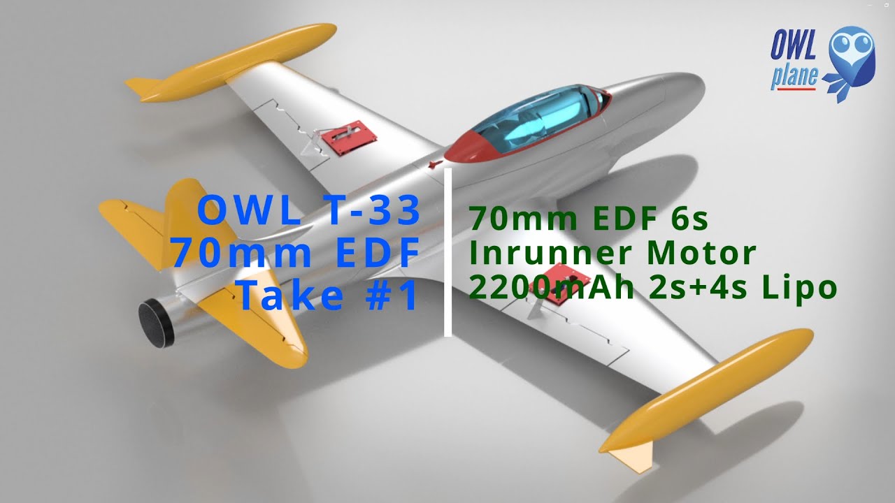
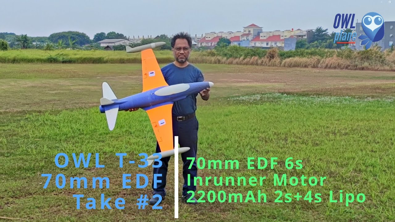
OWL T-33 70mm EDF
The OWL T-33 Shooting Star (70mm EDF) is engineered for maximum flexibility, allowing pilots to choose their preferred power system and battery configuration without compromising on structural integrity.
Versatile Power & Hardware Compatibility
The T-33 is designed to accommodate a wide range of 70mm EDF units and battery setups:
EDF Support: The fuselage is optimized for 70mm EDFs and is compatible with both removable and fixed intake lips.
Battery & CoG: To achieve the ideal Center of Gravity (CoG), we recommend a battery weight of approximately 400g or more.
Recommended Setups: 4S 3300mAh or 6S 2200mAh LiPo.
Adjustability: The model can accept various battery weights as long as you can achieve the suggested CoG by adjusting the position of the battery and ESC.
Advanced “Digital Balsa & Foam” Construction
We continue to utilize our innovative “Digital Balsa and Foam” approach for this model. This design philosophy has received excellent feedback from our community for its ability to:
Increase Durability: The internal structures are significantly stronger than traditional 3D-printed plane designs.
Maintain Weight: It provides this added strength while keeping the All-Up Weight (AUW) comparable to our ultra-light “Digital Balsa” models.
Maintenance Tip: To protect the airframe from landing-zone abrasions, we suggest applying fiber tape to the underside of the fuselage.
Launching & Flight Success
To ensure a successful maiden and long-term enjoyment of your T-33, we recommend the following:
OWLplane Catapult Launcher: If you are new to EDF jets, our catapult system is the best way to eliminate “human error” during takeoff. It allows you to keep your hands on the control sticks from the moment of launch.
The Maiden Strategy: We highly suggest using the catapult for your initial flights. Once you have successfully trimmed the aileron and elevator surfaces, the model becomes much more predictable and easier to hand-launch if you choose to do so.
In general, this model must be printed with LW-PLA/ePLA-LW/PolyLight 1.0 filament only (you still may want to experiment printing some parts with PLA * for example printing wings with PLA for having extreme maneuver *). It is not with landing gear model (it is hand launch or catapult launch type of model),
Videos and Pictures
Flying Play List
2:53
2:42


Digital Balsa and Foam Series
Printing Profiles with Gyroid Infill :
As you can see from the pictures below, they illustrate a 3D printed part when using gyroid infill and ribs. You can pick infill percentage to you preferences where the higher you set it will be stronger. To get optimal result, we also still use ribs so that we will achieve parts using optimal gyroid infill percentage. With having gyroid infill, we have tried to use top and bottom layers. The good news is that the AUW is still acceptable for the jet and allow it to use like lego style blocks to assemble.
We run some research and experiment with some number of setting values for infill percentage. Final values will be used in our OWLplane slicer profiles. Feel free to increase or decrease the values including playing with other settings if you feel better than ours (we are happy listening / getting your input/feedback, so keep us posted about your build in our facebook group).

*) Below is from F16 part for illustration.


Like Playing Lego :
As explained above, click the right side youtube video showing how to assembly the fuselage like playing “lego” blocks.
Expected Some Stringing but Easy to Clean :
Since active foaming filaments such as LW-PLA is not affected by retraction, some stringings are expected. The good news is that they are easy to clean compared to printing with standard PLA/PLA+.
*) below are sample parts from F16 model.
- Suggested using knife to clean initially.
- Once completed using knife, continue using sandpaper for sanding some strings that still attached to skin.
- Sandpaper could also used to make smoother skin.
- For the plug-in blocks, also use sandpaper to eliminate excessive materials.


Sandpaper Cleaning the Excessive Materials Surrounding Plug-In Blocks :
Sanding parts would make assembling much easier and also cleaner. Excessive materials can be found on the top surfaces. For example, the circle in the picture need to sand so that there is no need to push the part harder later to fit into the next part.
*) a sample part from F16 model.

Sand The Surfaces To Get Smooth Ones :
Comparing surfaces before and after sending it. LW-PLA material let you smoothing surfaces where it would not be applicable when sanding standard PLA or PLA+.


Specification and Some Details
- Wing Loading : 68.4-79.1gr/dm^2.
- AUW/Flying Weight : 1,650-1,850gr (with battery 3300mAh 4s to 2200mAh 6s).
- Wing Area : 23.4dm^2.
- Wing Cube Loading (WCL) : 14.1-16.3
- Flight Performance Category : Racer.
- Radio Channels : Throttle, Aileron and Elevator.
- Length : 1,056mm.
- Wing Span : 1,240mm.

Spar Requirements :
- 1 x 8mm OD and with 475mm long fiber carbon tube as front fuselage and wing spar.
- 1 x 8mm OD and with 475mm long fiber carbon tube as back fuselage and wing spar.
- 2 x 6mm OD and with 444mm long fiber carbon tube as wing spars.
- 1 x 6mm OD and with 350mm long for stabilizer spar.
Locking Belt for Attaching Wings to Fuselage :

Aileron/Wing Control Surfaces Rods:

Elevator/Horizontal Stabilizer Control Surfaces Rods:

Electronic Positions :
Feel free to locate the electronics for getting the correct CoG.

70mm EDF Bracket and Installation :
Below pictures show how 70mm EDF installed into the fuselage.


*) Pictures above are from OWL ViperJet 70mm EDF for illustration only.
Two sets of EDF brackets can be used. The one with intake lip removed or the one with intake lip intact.
You can find the bracket STL files under “OWL T-33 70mm – SUPPORT ver 1.0\EDF BRACKETS”.

*) For illustration only from 64mm EDF
Below showing 70mm EDF and their brackets. You do not need to glue the fixed intake lip EDF into its bracket but you need to screw left and right side arms before attaching to the fuselage so that the bracket will not easily separated from its bracket.
Left side : using screws to attach to the bracket for EDF with fixed intake lip.
Right side : using hot glue for 70mm EDF with no intake lip (removed intake lip).


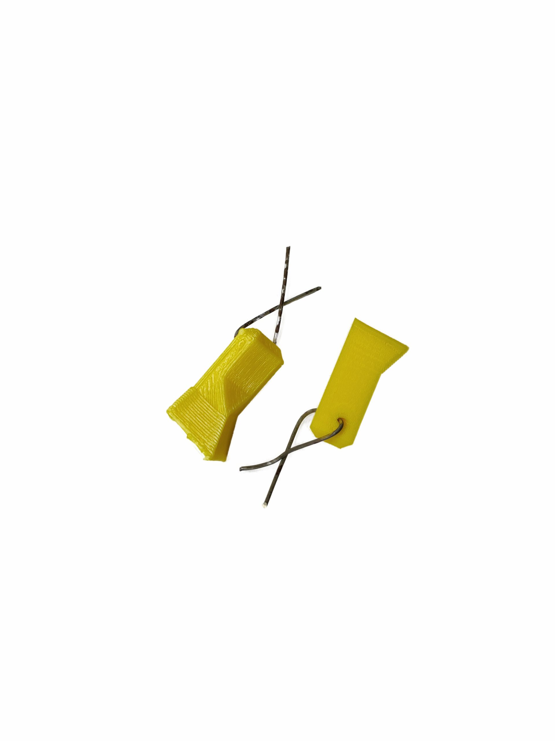
EDF Hatch Support Rods :
Please insert steel support rods about 1.5mm OD into the provided holes to make parts stronger as shown by the pictures below :


*) Pictures above are from SuperOWL Jet 70mm EDF for illustration only.
Center of Gravity (CoG) :
- CoG is 84mm from Wing Root Leading Edge (see the pictures below).


How to Launch OWL ViperJet 70mm EDF Model :
Two methods are suggested to launch the model. The first one is to use OWLplane Catapult Launcher. Please visit OWLplane Catapult Launcher product page menu under “SHOP & PRODUCT LIST” tab after hovering the mouse over (you can use your own Catapult Launcher so that you just need to print the hook adapter). The second one is by hand launching.
It is recommended to launch the model by utilizing OWLplane Catapult Launcher or your own launcher since it is human error free.
#1 – By Utilizing OWLplane Catapult Launcher.
Watch the following videos how easy it is to launch the rc model with OWLplane Catapult Launcher and human free errors.

#2 – By Throwing.
Follow the following tips to launch :
– Lean your body backward.
– Put your fingers on designated locations (shown in the following section below).
– Start throwing by also moving your body forward.


*) Above pictures are illustration only, using 50mm BAE Hawk T1.
Printing and Preparing OWL ViperJet 70mm EDF Launcher Adapter :


If you plan to launch the model with your own catapult launcher, please print the parts shown on the right side from “OWL T-33 70mm – SUPPORT ver 1.0\CATAPULT ADAPTER” for the puller and need to glue the hook bar “T-33 HOOK # GR3” from “OWL T-33 70mm – STL, 3MF and G-code ver 1.0\1. FUSELAGE\STLs” directory to the fuselage.


Finger Resting for Hand Launching :
If you choose to launch by throwing, please put your fingers as shown in the following pictures.

Optional : Fiber Tape Protecting The Model During Belly Landing
By using fiber tape attached to the belly skin, it will protect a model during landing from rough surfaces. Not only protecting, you may no need to clean the belly after sometime by replacing it to get back clean.
We have tested it and really happy with the result. The model is still in a good condition after landing it on rough surfaces.
*) Using F16 belly part as illustration only.


Some Note for Slicing STL Files :
Default Value are :
– Retraction : Set enabled only to make “extra restart length = 0.05mm” (PrusaSlicer), “extra restart amount = 0.05mm” (IdeaMaker) or “retraction extra prime amount = 0.5mm^3” (Cura) to compensate loosing materials due to stringing issues.
– Heatbed: 55 degree C.
– Hotend: 245 degree C (you may want to change it between 240 – 250 degree C).
– Extrusion Multiplier : 0.55% (feel free to update this value).
– Extrusion Width: 0.40mm (feel free to find your preference value, but it will be around that value).
– Extrusion Height: 0.25mm (greater is faster but less stronger bonding).
– Printing Speed: 35mm/sec.
– Retraction Speed : 50mm/sec.
Weight and Time Estimation :
Following tables show the weight of printed parts, number of required filament rolls and time required to print. But the number may vary from printer to printer due to:
– Stepper Jerk value.
– Stepper Acceleration value.
– Steps per unit (either calibrated or uncalibrated).
– Extruder quality/condition.
– Nozzle quality/condition.
– Filament quality/condition.
– Etc.

Here are the summary table :

Klipper Firmware Does Not Accept “#” / Hash Character
Unfortunately the Klipper firmware does not accept the “#” / hash character when naming the file. More and more 3D printers nowadays and upcoming most likely will use the Klipper firmware where when using previous firmware such as Marlin, Prusa, etc. do not prevent it from processing.
Since our naming convention for our g-code files utilize the “#” character and already since we started the OWLplane, we still keep them until our new release models dated after July 2024 (after BD OWLjet 70mm 6s EDF).
No worry, to use our g-code files, just need to remove the “#” character, that is it !
Fore example :
“FUSELAGE-1 # P3_H15″ replace the file name with “FUSELAGE-1 P3_H15”
Note : no “#” character is used in the new file name.
How To Extract Our Zip Files
Somehow when the folder path is too long, files and directories can not be extracted directly to a destination directory. There is a workaround for this, just follow the guide below. What you need to follow is to double click zip file until you find the directory. From there, right click to invoke a “copy” command. After that, just copy and paste the directory into your destination directory. That is it !


Table of Contents
Update History
None.
Recommended Setup


- Motor Options : Powered with 70mm EDF 4s and 6s (see above but not limited to).
- Servo Options : 4 x 12gr servos for aileron (left and right) and elevator (left and right).
- ESC Options : ESC 80A, please consult to your EDF manual if safe enough to use that rated Ampere value.
- Battery Size : LiPo 4s 3300mAh or 6s 2200mAh rated 70C with weight around 400gr.
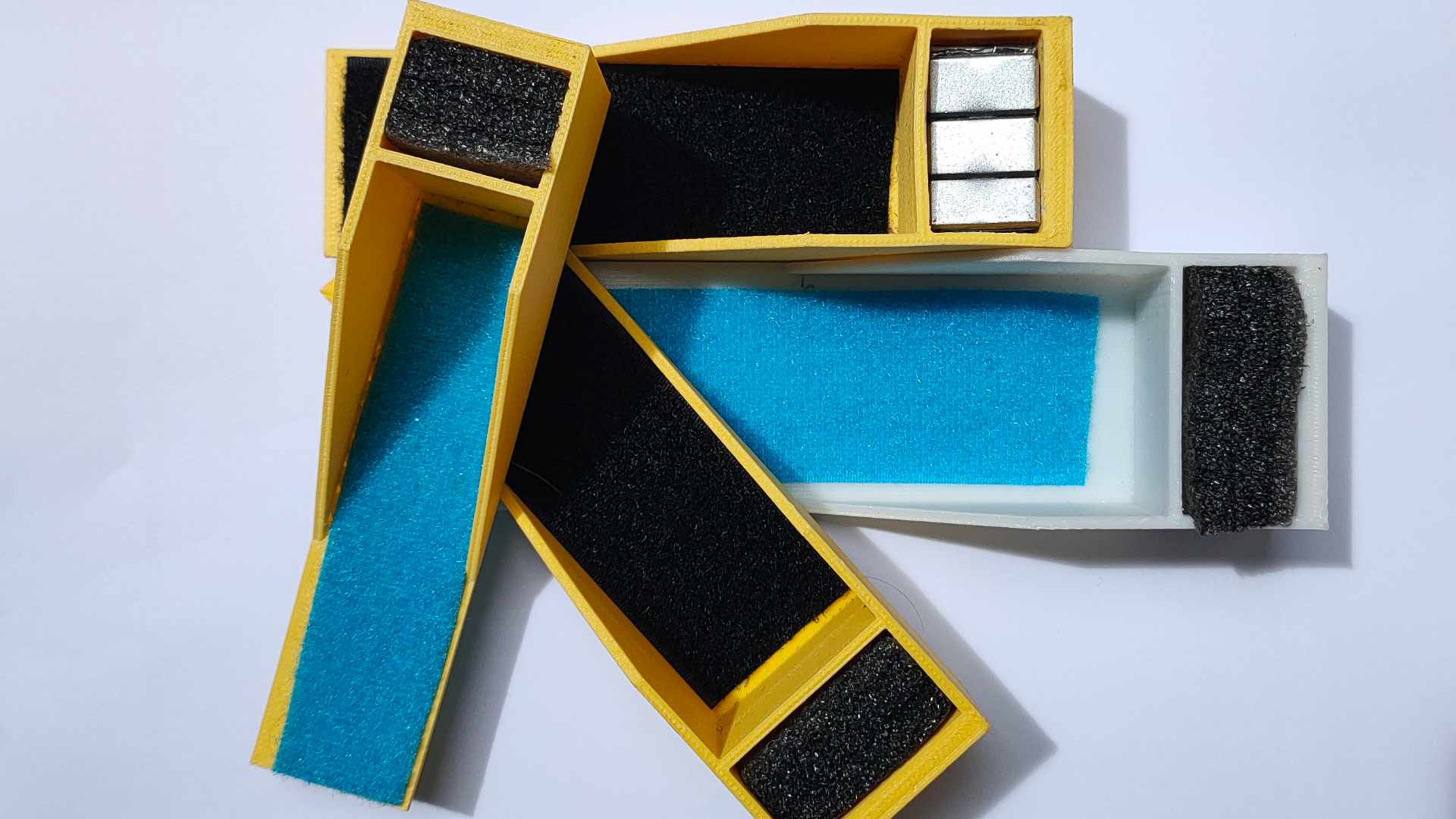
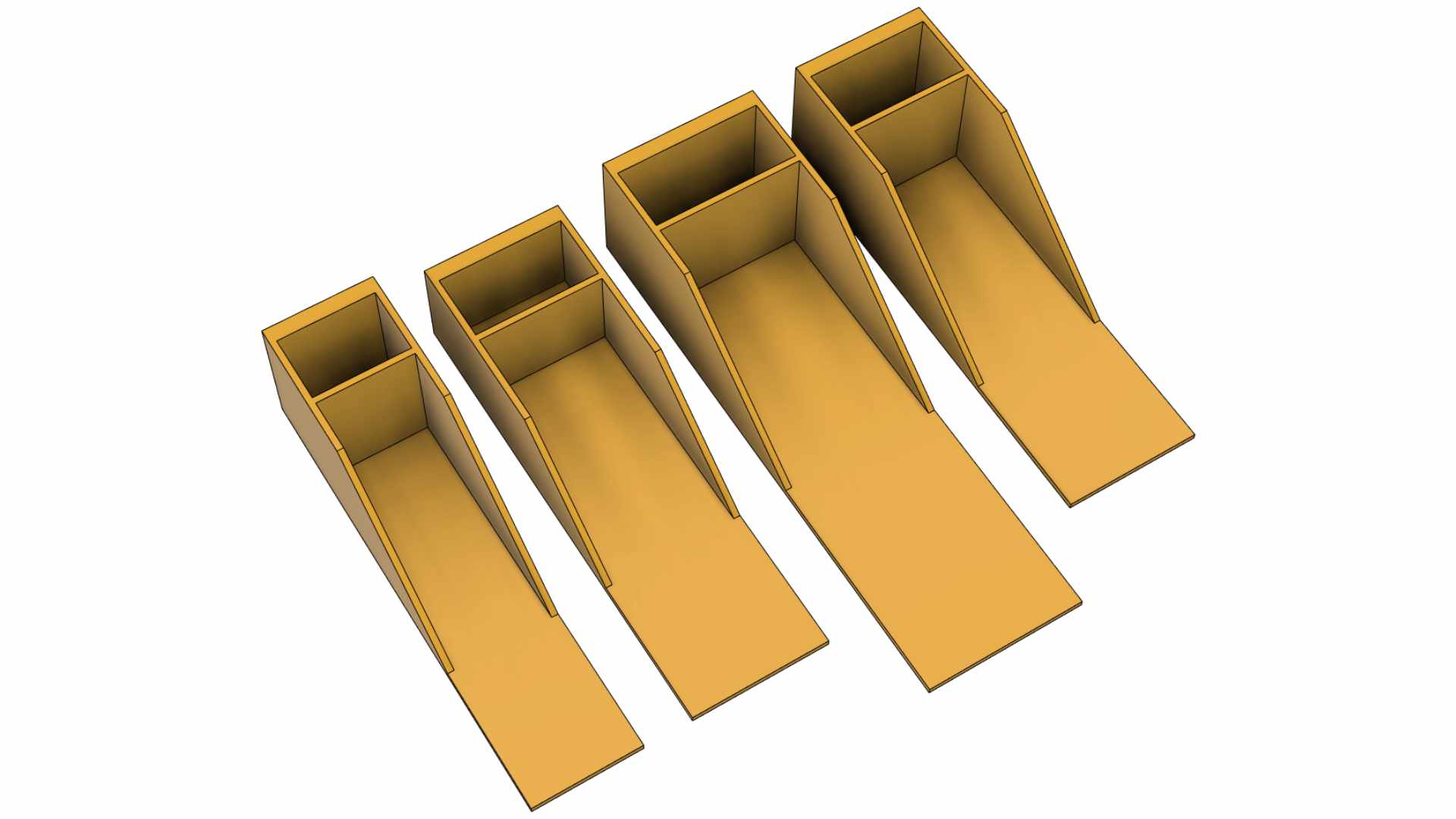
Battery Protector and/or Weight Balancer Holder for 2200mAh 3s/4s and 3300mAh 4s Battery :
One of challenges in 3D printed plane is where it has a wide range of possible total weight result. To solve this issue at the same time protecting your battery, the following STL files are created for your 2200mAh 3s/4s and 3300mAh 4s. Feel free to download and use the files (G-code files are also provided for Bowden or Direct Drive setup including STEP files).


Tools and Materials
- Printer, in general 210mm x 210mm x 210mm (W x L x H) for all OWLplane Models.
- Filament: LW-PLA from ColorFabb, ePLA-LW from eSUN and PolyLight 1.0 from 3DLabPrint.
- CA glue with accelerator. Use thick glue to join surface to surface. Use thin CA glue for coating the joint surface areas.
- Velcro sticker/polyester hook and loop peel-n-stick self-adhesive for locking the battery.
- Fine sandpaper.
- Sharp knife.
- Screwdriver and/or allen wrench for chosen screws/bolts.
- Pliers, needle-nose pliers, nippers.
- Steel bolt cutter.
- Dremel/rotary tool for cutting carbon fiber tubes and rod with more than 2.5mm.
- Electric drill, its drill-bit size from 1.5mm - 5mm and step cone drill.
- Propeller shaft reamer or hole puncher reamer.
Hardware Needed
For Fuselage and Canopy:
- Self tapping screws M3x25mm with their washers (optional) for mounting left and right wings including EDF hatch - 4x (2x wings and 2x EDF hatch).
- Ballpoint pen springs for Canopy - 1x.
For Aileron and Elevator Servos:
- 1.5- 2.0mm rod for aileron and elevator hinges (ER308L - TIG Stainless Steel Rod but preferred TIG Aluminum Rod instead).
- 1.5 - 2.0mm rod for aileron and elevator pushrod (ER308L - TIG Stainless Steel Rod).
- 2.0 - 2.5mm rod for aileron, horizontal stabilizer and canopy support (ER308L - TIG Stainless Steel Rod).
- Landing gear wheel stop set collar 6x2.1mm for aileron and elevator - 4x.
- Linkage stopper D2.1mm for aileron and elevator - 4x.
*) Illustration only
Assembly Figures
T-33 70mm Fuselage Assembly


T-33 70mm Wings Assembly


T-33 70mm Stabilizer Assembly


T-33 70mm Canopy Assembly

