
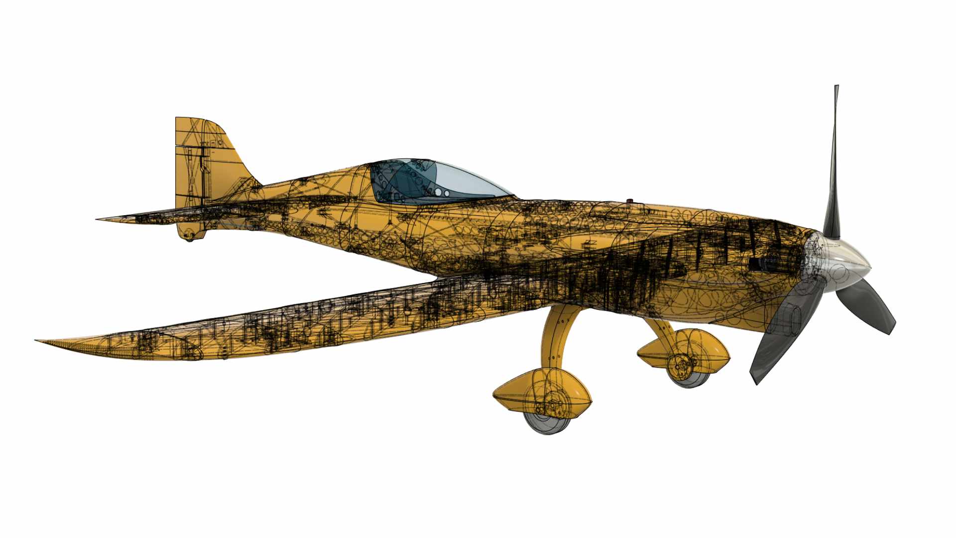
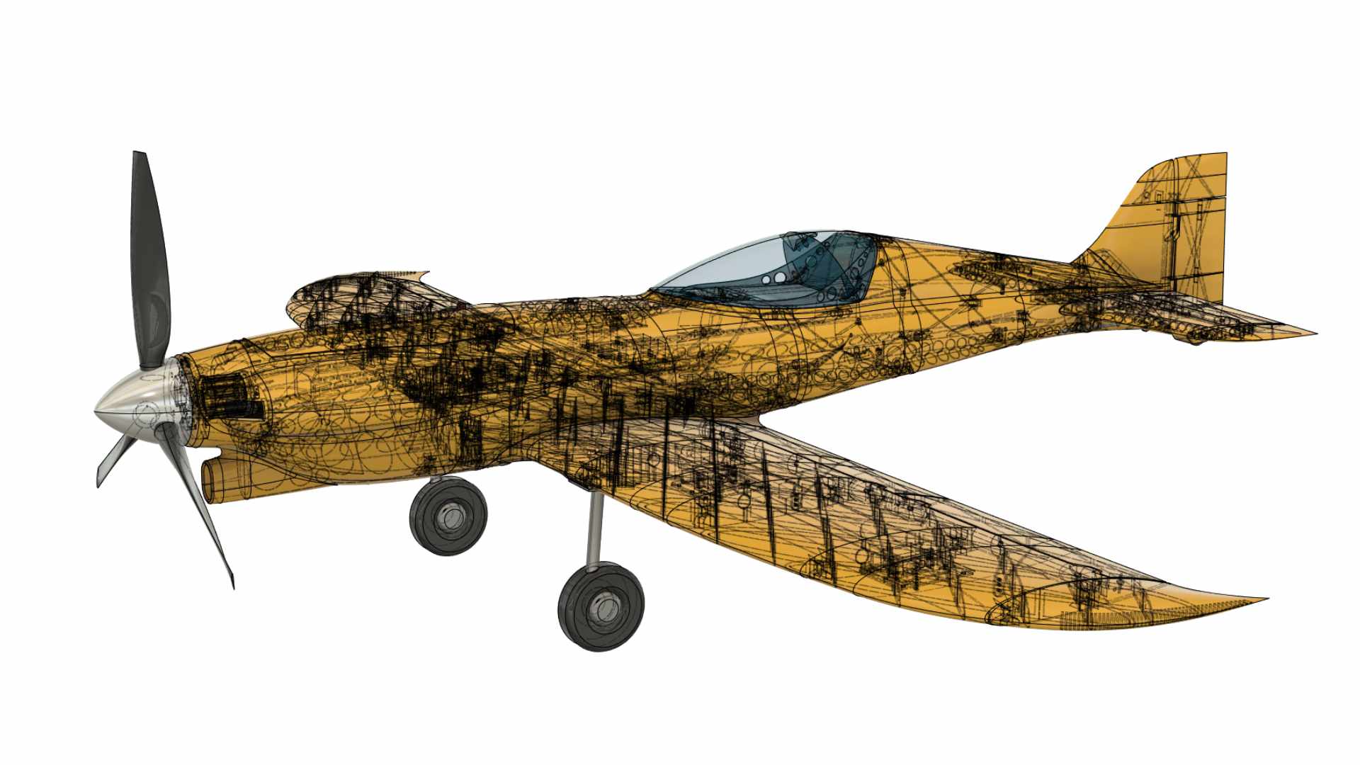
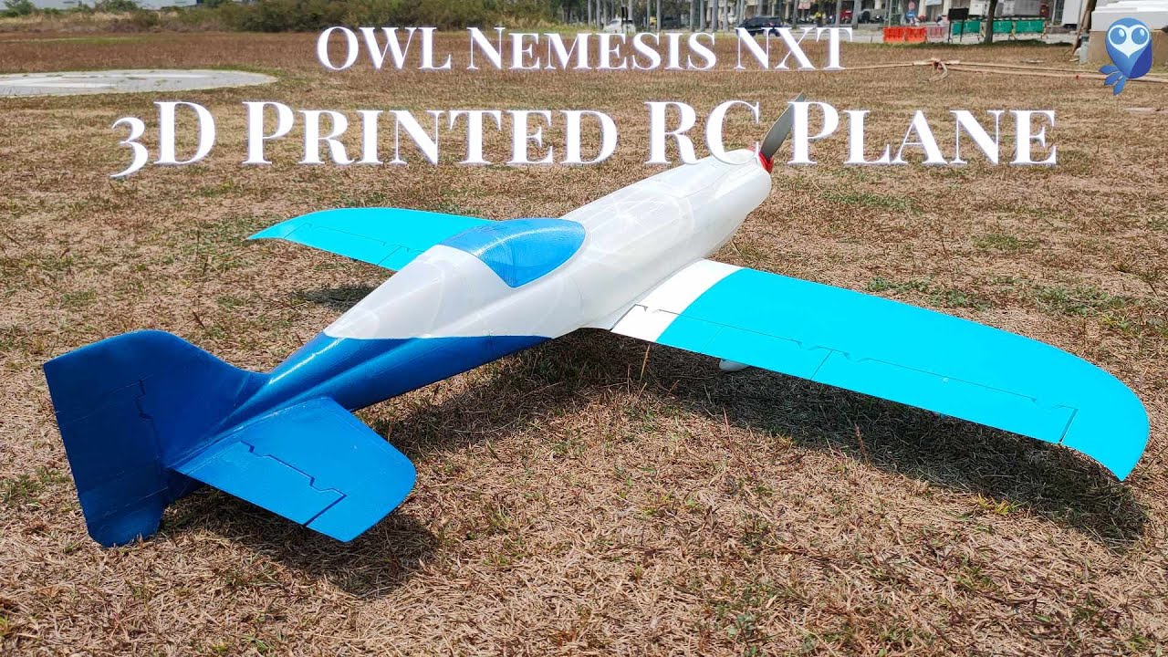
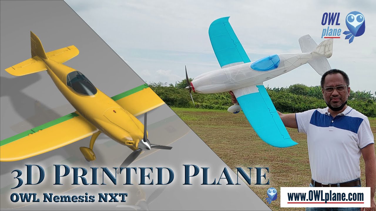
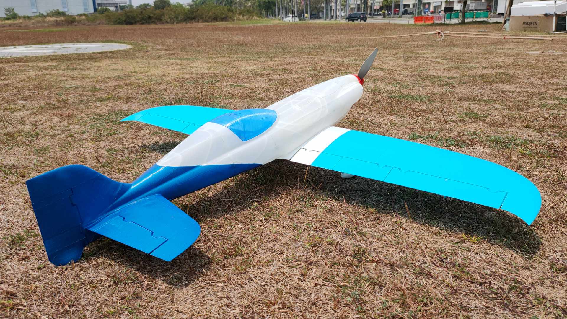
OWL Nemesis NXT
~ PLA Series Model ~


OWL Nemesis NXT Videos and Pictures
OWL Nemesis NXT Flying PlayList
3:19
2:25


Specification

Please use only profiles provided for Nemesis NXT when printing with 0.32mm extrusion width (it needs horizontal size compensation to get internal structures printed correctly) !
Try to avoid printing all parts with 0.40mm extrusion width for getting best experience with the model. If still want to print with that extrusion width than try to print some parts with LW-PLA, ePLA-LW or PolyLight 1.0 such as stabilizers and wings whenever possible/strong enough (both are supported with spars).
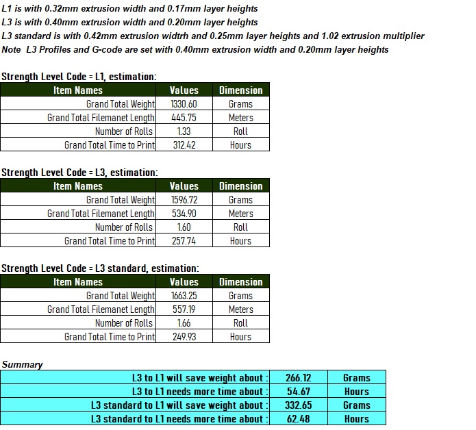
OWL Nemesis NXT flying videos posted on the youtube were printed with all PLA+ and 0.32mm extrusion width. It saves significant weight (see the “Weight and Time Estimation – Summary Table below”) !
If printed with 0.3 extrusion width, 3548 outrunner motor is more than enough and if printed with 0.4 extrusion width, 4248 is better (more power). Please note that 4248 outrunner is about 70gr more weight than 3548. 4248 outrunner motor helps on getting correct CoG with less battery weight.
- Wing Loading : 84.6-100 gr/dm^2.
- AUW/Flying Weight : 2200 gr (printed with 0.32mm extrusion width and 3300mAh 4s) and 2600 gr if printed with 0.4mm extrusion width.
- Wing Area : 26 dm^2.
- Wing Cube Loading (WCL) : 16.6-19.6.
- Flight Performance Category : Sport Aerobatic.
- Radio Channels : Throttle, Aileron, Flap, Elevator, Rudder and Main Landing Gears.
- Length : 1100 mm.
- Wing Span : 1289 mm.
Landing Gear Options :
- w/ 3D printed main landing gear.
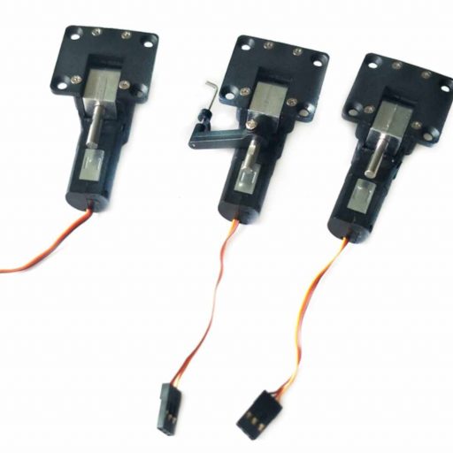
- w/o servoless retractable main landing gear.

Two Style Nemesis NXT – w/ or w/o Front Intake :
- w/ Front Intake : “FUSELAGE-0 # N0” and “FUSELAGE-1 # P3_H15”.
- w/o Front Intake : “FUSELAGE-0 # N0 – no intake” and “FUSELAGE-1 # P3_H15 – no intake”.

Spar Requirement :
- Wing Spar : 1 x 10mm OD – 1000mm long fiber carbon tube.
- Horizontal Stabilizer Spar : 1 x 5mm OD – 380mm long fiber carbon tube.


Servo Bridge and 4mm Wing-FL Screw Installation :
- 4mm Nut Holder and “FUSELAGE-3 # P3_H15”, best gluing this before doing fuselage assembly (see the assembly video).
- Hot glue, use hot glue after attaching with CA glue to secure but use your preferred method to attach anyway.
- Suggest to use hot glue for quick servo bridge installation.


Warning Regarding Motor Installation :
- This is seriously critical when installing motor mount ! The Motor Mount wall is already designed to prevent any unwanted move such as sudden pitch down or up when increasing the motor power. The thrust line is designed for certain up or down and also 2 degree right horizontally. The gap will introduce incorrect thrust line causing problem when flying.
- If your motor can not move freely, try to enlarge the shaft hole on the motor mount and remount the motor right after.
- If not happy with the default thrust line, feel free to modify it. The motor mount STEP file is provided for you under “SUPPORT\MM” directory.


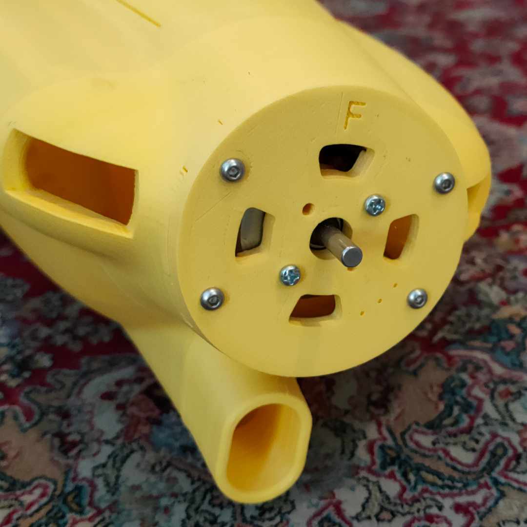
Motor Mount Installation :
- Make sure that “F” letter is at the front side.
- STEP file is provided if you would like to change the thrust line angle.
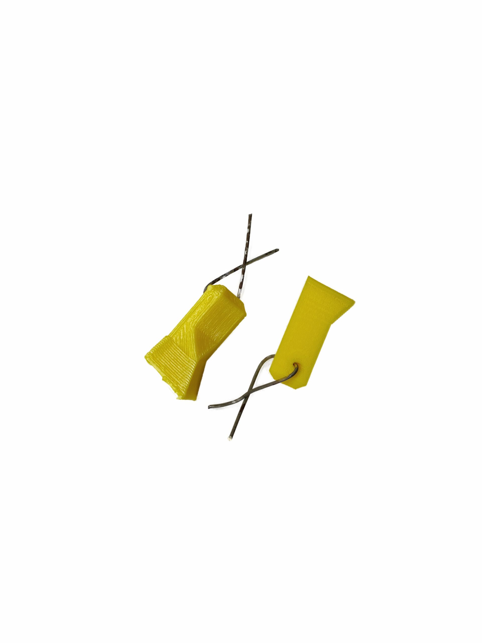
Special Note for Rod Hinges :
- Please use 1.1mm Rod for creating all control surface hinges when 1.5mm Rod does not fit into the holes.
- If printed with 0.4mm extrusion width, may/can use 1.5mm Rod instead.
- Just prepare both 1.1mm or 1.5mm Rod to create the hinges and pick whichever best fit.
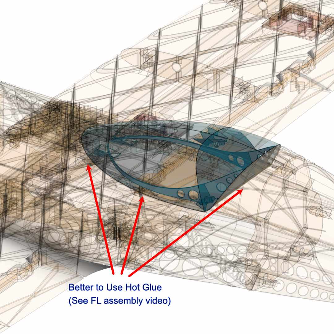
Canopy Assembly :
- Suggest to use hot glue instead since hot glue is very good filling the gaps.
- Watch assembly video for more details (during fuselage assembly).
Special Note where Printed with 0.4mm Extrusion Width :
- Due to get correct CoG, best to use 4248 650kv than 3548 <xxx>kv (more weight on the nose).
- 5-6s battery 2200mAh is suggested to use (weight about 420grams) with that outrunner motor.
- Right side figure shows 6s 2200mAh battery from 2 batteries 2s 2200mAh and 4s 2200mAh in series with total weigh is about 420gr.
- Suggested propeller to use is 12×6.


Center of Gravity (CoG) :
- CoG is 64mm from Wing Root Leading Edge.
- Start with more solid flying and adjust gradually during the next flight.

Weight and Time Estimation :
Following tables show the weight of printed parts, number of required filament rolls and time required to print. The numbers are taken from S3D slicer calculation. From experience, actual numbers show about -5% less than depicted in the table. But the number may vary from printer to printer due to:
– Stepper Jerk value.
– Stepper Acceleration value.
– Steps per unit (either calibrated or uncalibrated)
– Extruder quality/condition.
– Nozzle quality/condition.
– Filament quality/condition.
– Etc.
For sure the relative number are useful when deciding to accept the total strengths or weights when printing. Picking higher strength to some parts are necessary to avoid breaking during high impact landing or sharp maneuver for example.
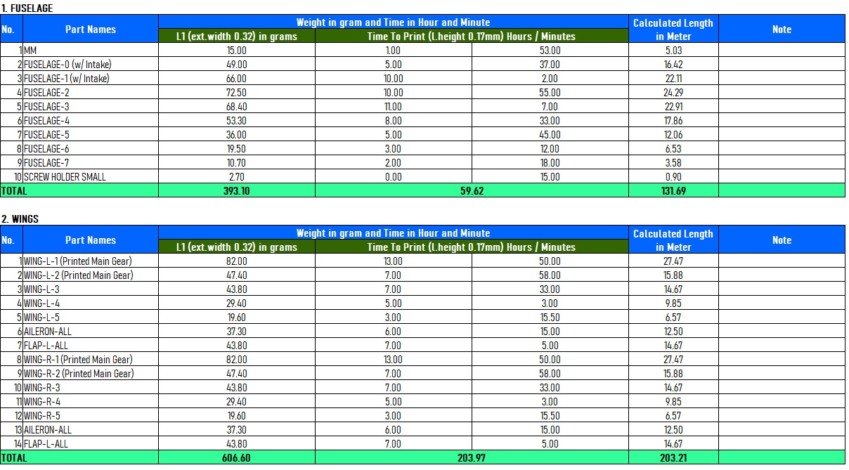

Here are the summary tables:
Klipper Firmware Does Not Accept “#” / Hash Character
Unfortunately the Klipper firmware does not accept the “#” / hash character when naming the file. More and more 3D printers nowadays and upcoming most likely will use the Klipper firmware where when using previous firmware such as Marlin, Prusa, etc. do not prevent it from processing.
Since our naming convention for our g-code files utilize the “#” character and already since we started the OWLplane, we still keep them until our new release models dated after July 2024 (after BD OWLjet 70mm 6s EDF).
No worry, to use our g-code files, just need to remove the “#” character, that is it !
Fore example :
“FUSELAGE-1 # P3_H15″ replace the file name with “FUSELAGE-1 P3_H15”
Note : no “#” character is used in the new file name.
How To Extract Our Zip Files
Somehow when the folder path is too long, files and directories can not be extracted directly to a destination directory. There is a workaround for this, just follow the guide below. What you need to follow is to double click zip file until you find the directory. From there, right click to invoke a “copy” command. After that, just copy and paste the directory into your destination directory. That is it !


Table of Contents
Update History
No Update for this model yet
Recommended Setup

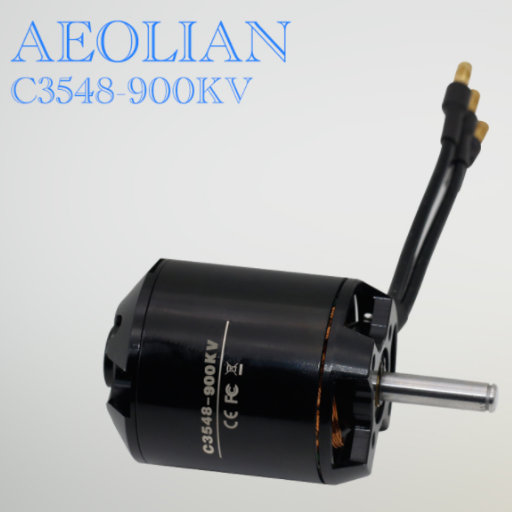


- Motor Options : when printed with 0.32mm extrusion width *** 3548 with 790KV/900KV/1100KV motor type (already tested it with 900KV, should work also with 790KV - 1100KV, see options above but not limited to) *** or when printed with 0.4mm extrusion width *** 4248 with 650kv and 5-6s LiPo battery ***.
- Servo Options : 7 x 12gr servos as follow 2 x 12gr servos for ailerons, 2 x 12gr servos for flaps, 2 x 12gr servo for elevator and 1 x 12gr for rudder (see some options above but not limited to).
- ESC Options : ESC with 60A, just pick your favorite ESC but make sure that rated at least 60A or see the motor specification.
- Propeller Size for 3548 motor : depending on your motor KV. For 900KV above, tried with 12x6 and also 11x7, it works great with 4s LiPo battery (suggestion : choose lower KV to get lower temperature for the same propellers especially when you print the motor mount with PLA and use low quality spinner).
- Propeller Size for 4248 motor : 13x6 or 13x8 with 5s LiPo battery or 12x6 with 6s LiPo battery.
- Battery Size : 4s - 6s (use 4s for 3548 and 5s-6s for 4248), see below weight requirement.
Printed with 0.4<x>mm extrusion width (either 0.4mm nozzle or 0.3mm nozzle) – more weight needed on the nose side.
- Outrunner 3548 : required battery weight around 550gr.
- Outrunner 4248 : required battery weight around 420gr.
Printed with 0.32mm extrusion width (either 0.4mm nozzle or 0.3mm nozzle) – less weight needed on the nose side.
- Outrunner 3548 : required battery weight around 400gr.
- Outrunner 4248 : required battery weight around 300gr.
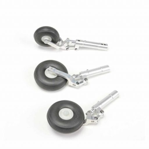
How to Select Servoless Retractable Landing Gear and Oleo Legs
- If picking Freewing L-39, only main gears that can be used (the nose gear can be used for OWL TL-Ultralight Stream model if purchased the model).
- Please do mix and match between servoless retractable landing gear and oleo legs. You need to make sure that they have the same pins/shaft.
- Please ignore part for nose retractable landing gear from the tab below (the model does not use nose landing gear).


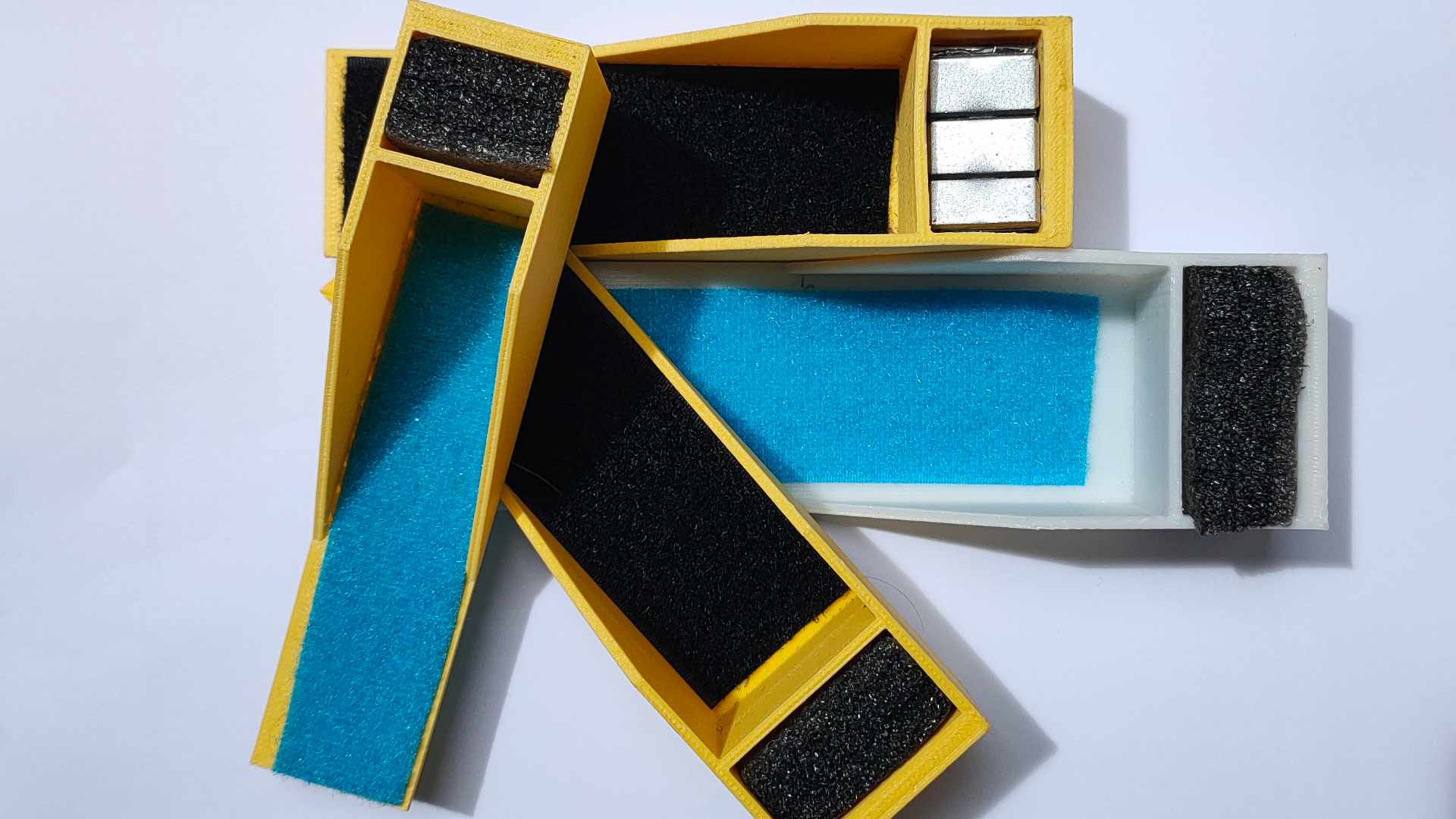
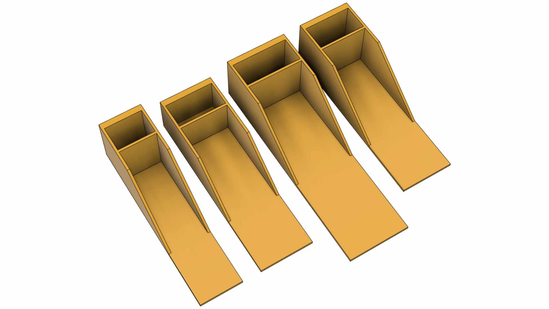
Battery Protector and/or Weight Balancer Holder for 2200mAh 3s/4s and 3300mAh 4s Battery :
One of challenges in 3D printed plane is where it has a wide range of possible total weight result. For example, the plane printed with 0.40mm comparing to 0.32mm extrusion width may end up the CoG moved about 2cm – 3cm backward with using the same battery. You may need to move the battery forward or add more weight at the nose to get back the CoG to its previous location. To solve this issue at the same time protecting your battery, the following STL files are created for your 2200mAh 3s/4s and 3300mAh 4s. Feel free to download and use the files (G-code files are also provided for Bowden or Direct Drive setup including STEP files).
Tools and Materials
- Printer, in general 210mm x 210mm x 210mm (W x L x H) for all OWLplane Models.
- Filament such as PLA, ABS, HIPS and ASA (do not use silk PLA, it tends to be very weak in layer to layer adhesion).
- CA glue with accelerator. Use thick glue to join surface to surface. Use thin CA glue for coating the joint surface areas.
- Velcro sticker/polyester hook and loop peel-n-stick self-adhesive for locking the battery.
- Fine sandpaper.
- Sharp knife.
- Screwdriver and/or allen wrench for chosen screws/bolts.
- Pliers, needle-nose pliers, nippers.
- Steel bolt cutter.
- Dremel/rotary tool for cutting carbon fiber tubes and rod with more than 2.5mm.
- Electric drill, its drill-bit size from 1.5mm - 5mm and step cone drill.
- Propeller shaft reamer or hole puncher reamer.
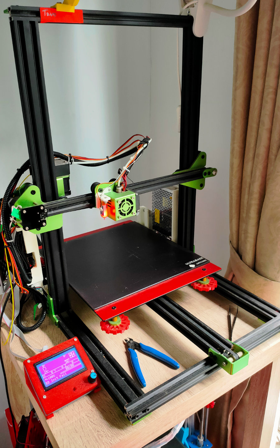
OWLplane Printers (for your ref.)
See figures below some printers used, created, developed and modified by OWLplane. Two group printers are set, the first one is utilized only for printing PLA/PLA+ and the other one is utilized to print with ABS, ASA and HIPS filaments (the one with enclosures). Just hover onto the figures to find more information about them.
Modified all Bowden setup printers into Direct Drive but leave Tevo Tornado and Anycubic Mega as is (still in bowden setup).
Hardware Needed
For Fuselage and Hatch:
- M3 x 0.5mm thread x 12mm screws with their washers for outrunner motor to motor mount wall - 4x.
- Self tapping screw M3x20mm or M2.5x20mm with their washers for mounting motor wall to the fuselage (Fuselage - N0) - 4x.
- 4mm OD and 56mm steel long shaft for main wheel axles - 2x (printed main gears optional).
- Landing gear wheel stop set collar 9x4.1mm for main wheel axles - 4x. (printed main gears optional).
- 2.0mm OD and 36mm steel long shaft for tail wheel axle - 1x.
- Landing gear wheel stop set collar 9x2.1mm for tail wheel axles - 1x.
- Ballpoint pen spring for Motor Hatch - 1x.
For Wings (except the control surfaces):
- M4x35mm screw and washer for attaching Wings to the Fuselage - 1x.
For Aileron, Elevator and Rudder Servos:
- 1.1mm - 1.5mm rod for creating aileron, flap, elevator and rudder hinges (ER308L - TIG Stainless Steel Rod).
- 1.5mm - 2mm rod for creating aileron, flap, elevator and rudder pushrod (ER308L - TIG Stainless Steel Rod).
- Landing gear wheel stop set collar 6x2.1mm for aileron, rudder and elevator - 7x (optional).
- Linkage stopper D2.1mm for for flap, aileron, rudder, flap and elevator - 7x.
- 2.0mm-2.5mm OD shaft for creating pins connecting two parts for aileron and stabilizer.
*) Illustration only
3D Printed Motor Mount, Propeller Spinner and Collet
Motor Mount Requirement
Motor mount wall should be 3D printed with more heat resistance filaments such as ABS, ASA or HIPS. If your 3D printer does not have enclosure you may want to try with PETG filament (more heat resistance than PLA/PLA+). In case you still would like to use PLA, please do annealing process (not sure can do for standard PLA), some successful with HT-PLA/Hight Temp-PLA. Click here for you to read about annealing article.


Propeller Spinner and Collet Requirement
OWLplane does not provide STL file for printed propeller spinner due to our concern about strength, shape and uniform weight when spinning at high speed. Not all 3D Printer has really free of skew issues for all their axes. The skew issue generates uneven shape that will lead to problem when spinning. Good spinner should be available in your local hobby store or online store, even that spinner, you still need to balance it before using it.
Spinner and Collet Requirement :
1. 64mm diameter size spinner.
2. 5mm or 4mm shaft propeller collet (check your purchased motor shaft to pick the right size propeller collet).
Please watch the following Videos to balance your Propeller and Spinner:
Assembly Figures
OWL Nemesis NXT Fuselage Assembly

OWL Nemesis NXT Wing Assembly


OWL Nemesis NXT Horizontal Stabilizer Assembly


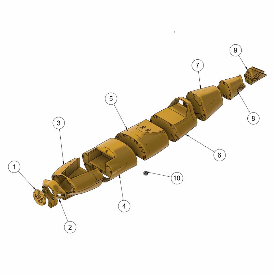
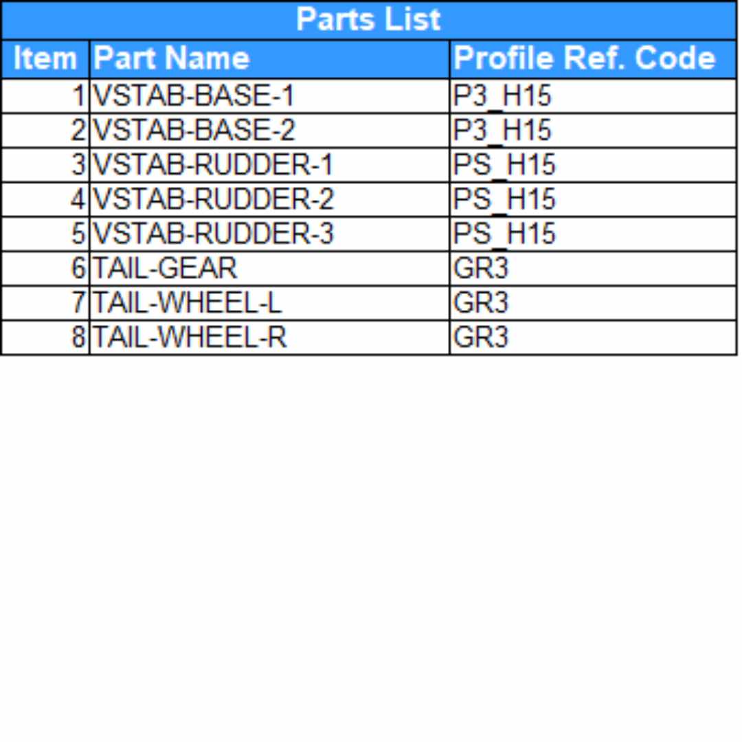
OWL Nemesis NXT Vertical Stabilizer Assembly

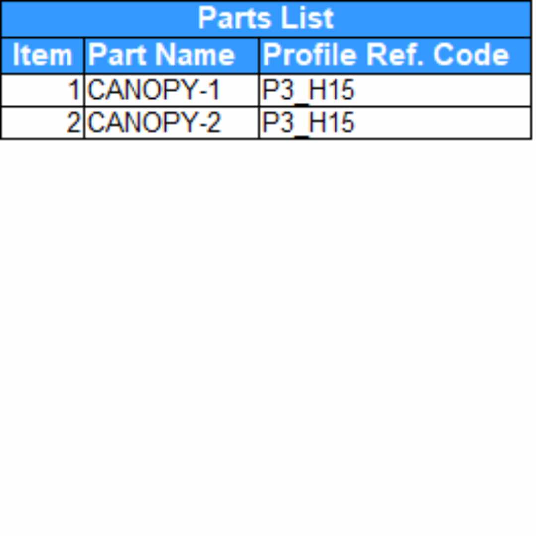
OWL Nemesis NXT Canopy Assembly

OWL Nemesis NXT Hatch Assembly


OWL Nemesis NXT Landing Gear Assembly

